IG746
Inductive Loop Detector For Urban Traffic (Including Public Transport)

The 4 channel loop detector IG746 is used for signal output in traffic light installations via switching outputs and CAN bus as well as for traffic counting.
FUNCTIONAL DESCRIPTION:
The CAN protocol is specifically designed for traffic control applications. Standard data contents are e. g. detection status, error status and detection edges with occupancy time respectifly time gap. In double loop systems additional data as vehicle speed, length and direction are transmitted. Via the CAN bus interface the full parameterization of the detector is also possible.
The detector processes the loops one after the other in a predetermined sequence (multiplex mode); i.e. there is always only one loop switched as inductance L to the LC oscillating circuit of the detector. Since there is always only current flow through one loop, the channels of a detector cannot interfere with each other.
If a metallic object is located within the range of action of the connected induction loop, the frequency of the LC oscillator also changes owing to reduction in the loop inductance. This change is determined by the detector evaluation circuit and, if the turn-on threshold is exceeded, a busy signal occurs on the switching outputs of the channel (electronic relay and open collector). Different output functions, e.g. presence signal and pulse signal are possible.
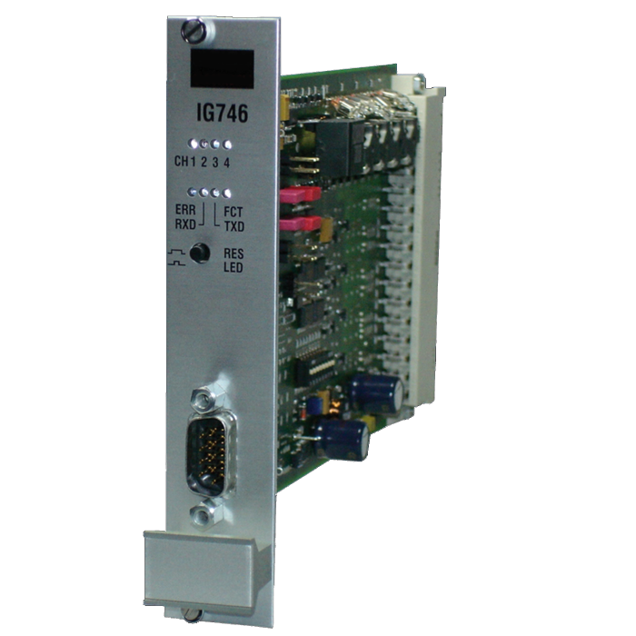
The IG746 is an inductive loop detector for the connection of up to four inductive loops and was specifically developed for traffic technology applications. It is functionally compatible with the previous model IG745/3 and available with 3 different terminal strips (DIN 41612, type F resp. C and B).
Version IG746 additionally offers a serial CAN bus interface. This version has a different terminal assignment and an extended functionality in comparison to the IG745/3. The bit rate is automatically recognized in a range of 10-500 kbps and the addressing can be effected by pins on the terminal strip.
The detector is configured using the serial RS232 interface on the front of the unit. The LoopMasteroperating program, which is free of charge, provides a convenient operator interface for modifying and displaying all parameters and diagnostic values. The configured parameters are stored in a non-volatile memory (EEPROM).
Benefits
Vandal-Proof
and Durable
Low Power
Consumption
Wide
Inductance Range
CAN Bus
Interface
Technical Details
Supply Voltage | Nominal voltage 24 V DC, range: 10 V DC - 38 V DC |
Power Consumption | 0.5 W - 1.0 W with 24 V DC |
| Loop inductivity | allowed range: 20 μH - 2000 μH; recommended range: 80 μH – 250 μH |
| Sensitivity | 0.5 % - 0.007 % (frequency change Δf/f0 in %) |
| Interfaces | CAN bus interface, service interface RS232 (PC-COM) |
| Outputs | Switching output per channel: potential free, electronic switch contact and open collector collective error message: potential free switch contact; optional: open collector |
| Dimensions | 19“ slot board (100 mm x 160 mm), Height: 128 mm, Length: 190 mm, Width: F type 25 mm (5 TE), B type 20 mm (4 TE), optional: 4 / 5 TE |
| Operating / Storage temperature | -25°C to +80°C / -40°C to +80°C |
| Protection class | III (low voltage < 60 V DC) |
| Installation | 19“ rack, installation in a housing or cabinet with IP54 is required (pollution degree 2) |
| Terminal strip | - F type, DIN 41612, 48 pole 3 rows, - optional: C type, DIN 41612, 32-/48 pole, 2/3 rows - optional: B type, DIN 41612, 64 pole, 2 rows |