PLD32
Circuit Board Detector for Applications in Integrated Electronic Control Systems

The 2-channel circuit board detector PLD32 was designed for vehicle access control for door, gate, and barrier, for vehicle detection depending on traffic direction and for safeguarding and monitoring e.g. of conveyor systems and car-wash plants.
FUNCTIONAL DESCRIPTION:
The induction loop detector PLD32 analyzes the loops in the ground, working as inductivities of a high frequency oscillating circuit. The metal body of a vehicle passing the loop causes a characteristic change of circuit frequency. The loop detector analyzes it and sends a switching signal to the potential free relay output. This is also displayed at the front panel LEDs.
The loop signals are analyzed by a microprocessor. When the detector is switched-on an automatic alignment with the connected inductive loop is executed.
There is no interference of loop signals since the dual-channel version PLD32 analyzes the loops in a defined order (multiplex mode) so that only one loop is active at one time.
Via rotary and DIP switches on the front the detector can be comfortably set or via serial interface on the front of the device all current parameter and diagnosis values can also be set and readout.
This is done by means of the LoopMasteroperating program which is available free of charge and which additionally offers extensive loop and detector analysis functions. The trend-setting customizing allows an individual configuration and setting of operating elements and functions.
Comfortable operation -
„LoopMaster“ Program
Direction
Signal
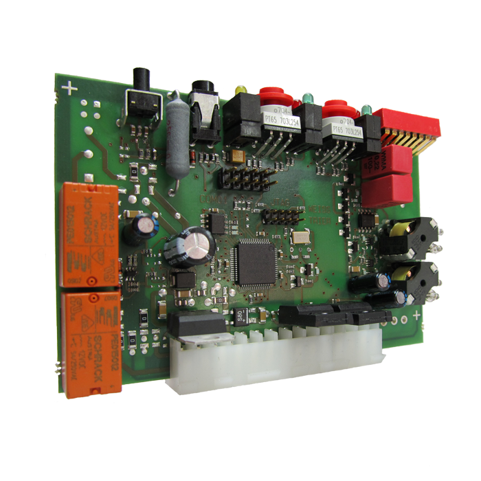
Compact
Design
Sensitivity
Boost
- Compact design
- Molex-connector for easy installation and adaptation
- Reliable data acquisition independent of environmental influences
- Intuitive pre-configuration without supply voltage and easy initial operation
- Fast automatic tuning after switch-on
- Wide adjustable range of response sensitivity
- Sensitivity boost
- Selectable relay functions: Permanent or impulse mode, impulse signal when leaving the loop, switchable turn-on / turn-off delay, closed / open circuit principle
- Continuous adjustment of frequency drifts because of e.g. changing temperature
- No interference of loop frequencies due to „multiplex mode“ (only IG326)
- High noise immunity due to frequency adjustment and oversampling
- Permanent loop control and display via LED blink code for immediate detection of inductive loop failures
- (loop short-circuits, loop disruptions, operational disturbances, alignment time)
- Direction signal
- Wide inductivity range: 20 μH - 2000 μH
- Simple simulation mode to test peripherie
- Comfortable operation by means of „LoopMaster“ program
- Customizing: Individual adjustment and confi guration of switch functions
Technical Details
Power supply | 24 V AC/DC |
Power consumption | 24 VAC/DC: < 3,0 VA |
Dimensions | Height: 70 mm, Width: 100 mm, Depth: 22 mm |
Operating / storage temperature | -25°C to +70°C / -40°C to +80°C |
Connections | 14-way Molex bar (Type 2145/3215 KK 3.96mm) |
Weight | 70 g |
Inductivity range | Permissible range: 20 μH to 2000 μH, recommended range: 100 μH to 300 μH |
Sensitivity | adjustable in 7 steps, from 0.3% - 0.007% |
Interfaces | Service interface RS232 via optional service cable |
Adjustment | automatically after switching on the supply voltage, after pressing the reset button |
Output | potential-free relay contacts per channel, optional: Open Collector |
Display elements | LED red = loop error LED yellow = blinking when alignment / power - Display LED green = detection |