IG946
Inductive Loop Detector For Urban Traffic (Including Public Transport)
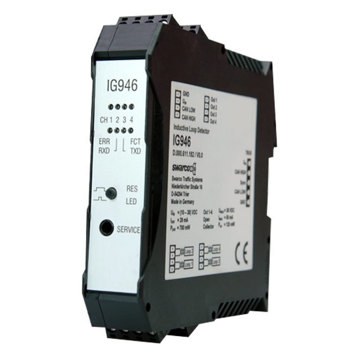

The 4 channel loop detector IG946 is used for signal output in traffic light installations via CAN bus and switching outputs as well as for traffic counting. The detector is designed for DIN-rail mounting and includes a complete overvoltage protection module for the inductive loops.
FUNCTIONAL DESCRIPTION:
The IG946CAN is an inductive loop detector for the connection of up to four inductive loops and was specifically developed for traffic technology applications.
The IG946 offers the functions and outstanding features of the SWARCO TRAFFIC SYSTEMS induction loop detectors in 19“ plug in technology as a DIN rail version and includes a complete overvoltage protection module in one device. This integration minimizes the wiring effort and significantly reduces the required space.
The IG946 has a serial CAN bus interface for data transfer. The bit rate is automatically recognized in a range of 10-500 kbps and the addressing can be effected by a DIP switch.
The CAN protocol is specifically designed for traffic control applications. Standard data contents are e. g. detection status, error status and detection edges with occupancy time respectifly time gap. In a double loop system, additional data such as vehicle speed, length and direction are transmitted.
A classification into bicycle / non-bicycle supplemented by speed and driving direction is possible when using a SWARCO bicycle loop system. Via the CAN bus interface the full parameterization of the detector is also possible.
The detector processes the loops one after the other in a predetermined sequence (multiplex mode); i.e. there is always only one loop switched as inductance L to the LC oscillating circuit of the detector. Since there is always only current flow through one loop, the channels of a detector cannot interfere with each other.
If a metallic object is located within the range of action of the connected induction loop, the frequency of the LC oscillator also changes owing to reduction in the loop inductance. This change is determined by the detector evaluation circuit and, if the turn-on threshold is exceeded, a busy signal occurs on the switching outputs of the channel (open collector). Different output functions, e.g. presence signal and pulse signal are possible.
The detector is configured using the serial service interface on the front of the unit. The LoopMasteroperating program, which is free of charge, provides a convenient operator interface for modifying and displaying all parameters and diagnostic values. The configured parameters are stored in a non-volatile memory (EEPROM).
Benefits
Vandal-Proof
and Durable
Low Power
Consumption
Wide
Inductance Range
CAN Bus
Interface
Technical Details
Supply Voltage | Nominal voltage 24 V DC, range: 10 V DC - 38 V DC |
Power Consumption | 0.7 W with 24 V DC |
| Loop inductivity | Allowed range: 20 μH - 2000 μH; recommended range: 80 μH – 250 μH |
| Sensitivity | 0.5 % - 0.007 % (frequency change Δf/f0 in %) |
| Interfaces | CAN bus data interface, service interface at front (USB adapter type KA_SERVICE_AJUSB optionally available) |
| Outputs | Switching output per channel: Open Collector |
| Dimensions | DIN rail enclosure: height: 99 mm, length: 114.5 mm, width: 22.5 mm |
| Operating / Storage temperature | -25°C to+80°C / -40°C to+80°C |
| Protection class | III (low voltage < 60 V DC) |
| Design | DIN rail mounting (TS35 EN50022), to be installed in housing or cabinet with IP54 (pollution degree 2) |
| Terminal strip | - MSTBT 2.5/4 (top and bottom) |