ATC CyberCabinet
Test and validate the functionality

For Traffic Signal Engineers, it is often a challenge to test ATC Cabinet Intersection Controller programs and visualize the results.
The ATC CyberCabinet software provides an Engineer with a software based solution to test and validate the functionality of an ATC Controller Unit database, without needing a full ATC5301 cabinet assembly in hardware.
Produce higher quality results in less time, while reducing or eliminating the need for call-backs once the intersection is operating.
- The ATC CyberCabinet supports five Input SIUs, two Output SIUs and a 32-channel CMU. Project and Map files store the configuration settings of each intersection.
Controller operation can be viewed and exercised at the SIU device level (Device View), or with a higher level overhead view of the intersection (Map View).
Device View
The Device view presents SIU inputs and outputs as separate forms (devices) with a control for each IO pin; name field, status icon, and checkbox.
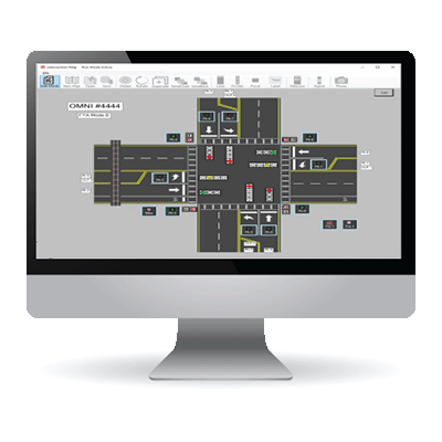
Map View
The map view elevates the display to a bird's eye view of the intersection geometry. Active icons are used to drive Detector, Ped, and Preempt inputs. Programmable signal face icons display RYG controller outputs.
Map Editor
A built-in map editor is used to constructs the Map view for a target intersection using a collection of active icons and road furniture icons.
A 32-channel CMU function is configured from the actual intersection Datakey parameters to validate compatibility with the Controller database.
Fault Detection
Conflict, Lack of Signal, Multiple, Y Clearance, Y+R Clearance, SB#1
Timeout, Local Flash, and Type 62.
Flashing Yellow Arrow (FYA)
Full support of Flashing Yellow Arrow including Virtual Channels.
Fault Log
A Previous Fault log is maintained to review any fault events captured by the CMU.
Datakey Load and Read
The CMU Datakey parameters can be read from a file or directly
from the Datakey using a supported Datakey Reader device.
A Serial Bus #1 ‘sniffer’ function captures the HDLC frames and displays the frame data and timestamp for detailed real‐time analysis.
Replay Mode
Serial Comm Trace logs can be saved and Replayed to repeat and analyze a signal sequence in detail.
The SIU Direct Mode can be used to monitor and control a physical SIU‐2218 device in a test cabinet.